The Rulbus is a simple input-output bus for peripherals, like an analog to digital converter. It is designed such that peripheral cards have a simple interface to the bus. Also, it is designed such that many microprocessor types can be connected to the Rulbus via a simple Rulbus Interface. Thus a single version of a peripheral card can be used with various types of microprocessors and microcomputer systems. more...
There are circa 100 different Rulbus modules. Some of the most popular are:
Several properties of a Rulbus module are:
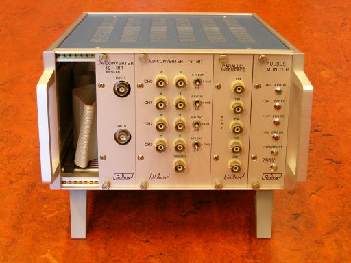
Based on an application's measurement and control requirements, various Rulbus modules are collected in one or more 14-inch racks. A rack may contain up to 12 single-width (35 mm) modules.
The picture below shows several Rulbus modules in a half-width
rack.
The Rulbus as a bus is a collection of several lines that make communication between a computer and the various Rulbus cards possible.
The bus consists of the following lines:
The Rulbus address space is thus 256 bytes (2^8). Two of these addresses are reserved:
There are Rulbus modules that only use one byte of the Rulbus address space, but there are also modules that occupy 32 bytes of the address space of 254 bytes. The address range a module uses, is determined when the module is made: it is programmed in the card's address GAL or PAL (programmable array logic).
If many modules are used together it may be difficult to assign all modules a proper address range and prevent address conflicts. To overcome this problem, the Rulbus addressing scheme is extended by giving each rack its own address.
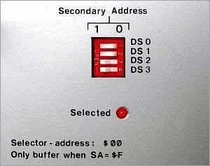
When more than one rack is used, each rack must have a unique address. The address of a rack is defined at its rear side via a 4-bit DIP-switch, so that rack addresses fall in the range 0--15.
Address 15 has a special meaning: the rack is always selected or active. In this case it must be the only rack connected to the computer--Rulbus interface.
If a rack has an address in the range 0--14, the rack must be specifically selected by a program before the cards it contains can be accessed. Note that the Rulbus Device Class Library takes care of this.
So with rack addressing, the range of available addresses is extended to 15 times 254, or 3810.
Nowadays, only two Rulbus Interfaces that connect to a PC are of interest:
The ISA Rulbus Interface is designed for the Industry Standard Architecture (ISA) slots of a PC. New PCs may not include ISA slots anymore, so a new Rulbus Interface was developed: the EPP Rulbus Interface.
The EPP Rulbus Interface is connnected to the parallel port of a computer (PC). For the interface to work, the parallel port must be configured to work in Enhanced Printer Port mode in the PC's BIOS, hence the EPP [IEEE1284].
The Rulbus Device Library supports both Rulbus Interfaces. At default the library assumes that the EPP Rulbus Interface is being used with the parallel port at address 0x378. If this assumption is not valid, the library must be informed what the proper interface type and address are. To this end the RULBUS environment variable can be defined. See section Defining the Interface.
| previous | top | next |